


Technical Support
Introduction to ToF Sensor Classification and Component Composition
Release time:
2024-08-30
Foreword: This article aims to provide readers with a comprehensive popular science article on the Time of Flight (ToF) system, from basic concepts to advanced knowledge covers the overview and classification of ToF systems as well as the discussion of various components in ToF systems.
ToF, or time of flight, is a method of measuring distance by calculating the time it takes for light to travel a certain distance in a medium. It is mainly used in optical ToF scenarios.
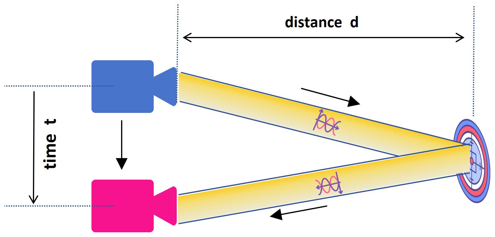
Figure 1.Basic principle of ToF
ToF is applicable to many fields. In consumer electronics, it is used for facial recognition, camera autofocus, proximity sensors, motion interaction, gesture recognition, AR, etc.; in robotics, it is used for vacuum cleaner robots, drone obstacle avoidance, as well as 3D scene scanning. In the industrial and security fields, it supports more including the automated robots, people counting, smart parking systems, smart transportation, smart warehousing, and dimensional measurement. Although lidar in smart driving also belongs to the ToF category, it is not the focus of this article.

In order to achieve the above distance measurement, a typical ToF system consists of the following parts:
- Transmitter (Tx): including laser light source (mainly VCSEL), laser driver circuit ASIC, and optical components (such as collimating lens or diffractive optical element) and filters for beam control.
- Receiver (Rx): including the lens and filter of the receiver(depending on the ToF system it may be a sensor such as CIS, SPAD or SiPM) and an image signal processor (ISP) for processing large amounts of data from the receiver chip.
- Power management: Stable current control of VCSEL and high voltage supply to SPAD, etc.requires strong power management here.
- Software layer: including firmware, SDK, operating system and application layer.
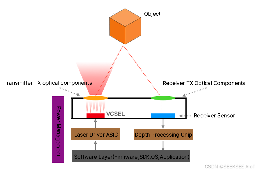
Figure 2:ToF system architecture
The architecture shows how a laser beam is emitted from a VCSEL, propagates through space after being modified by optical components, reflects off an object and returns to a receiver. By calculating the time difference in this process, distance or depth information can be obtained. It is worth noting that this architecture does not cover noise paths, such as noise caused by sunlight or multipath noise caused by reflections.
Although the principle of ToF seems simple - emit a light pulse and detect its return to calculate the distance - its complexity lies in distinguishing the returned light from ambient light. This challenge is solved by emitting light bright enough to achieve a high signal-to-noise ratio and choosing the appropriate wavelength to minimize interference from ambient light. Another approach involves encoding the emitted light so that it can be recognized when it returns, which is similar to the SOS signal of a flashlight.
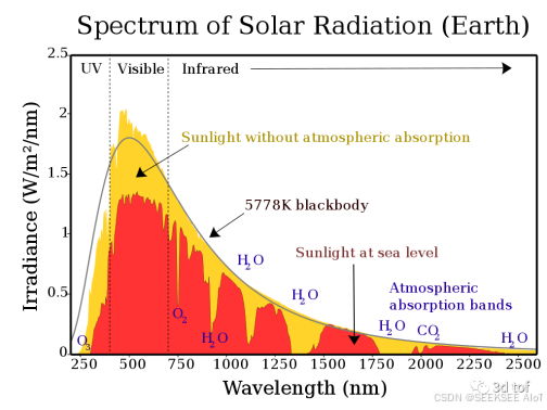
Figure 3. Spectrum of solar radiation
ToF systems can be classified based on the complexity of the information they provided as: 1D ToF, 2D ToF, and 3D ToF. 1D ToF represents simple single-point distance measurement, 2D ToF is common in vacuum robots that scan a line to map distances in the lower spaces of a room, and 3D ToF combines a 2D sensor array with an imaging lens to produce three-dimensional spatial information.
But, usually ToF systems are mainly classified based on their distance measurement technology as direct ToF (dToF) and indirect ToF (iToF), each with its own unique hardware and algorithmic approach.
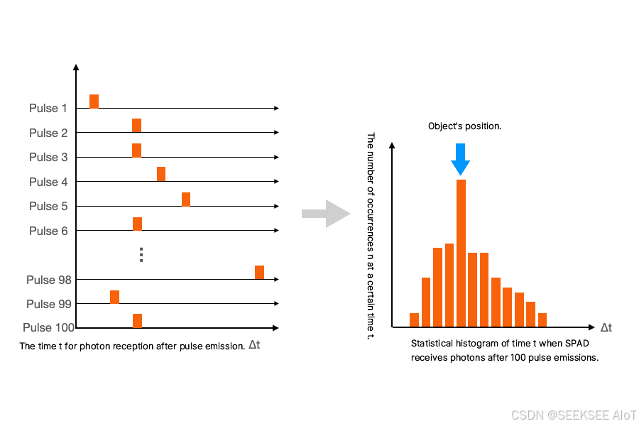
dToF
Direct ToF directly measures the time of flight of photons. Its key component, the single-photon avalanche diode (SPAD), is sensitive enough to detect individual photons. dToF uses time-correlated single-photon counting (TCSPC) to measure the time of arrival of photons and builds a histogram to infer the most likely distance based on the highest frequency of specific time differences.
iToF
Indirect ToF calculates the time of flight based on the phase difference between the transmitted and received waveforms, usually using a continuous wave or pulsed modulated signal. iToF can use a standard image sensor architecture to measure the intensity of light over time. iToF is further subdivided into continuous wave modulation (CW-iToF) and pulsed modulation (Pulsed-iToF). CW-iToF measures the phase shift between the transmitted and received sine waves, while Pulsed-iToF uses a square wave signal to calculate the phase shift.
dToF and iToF each have their own unique advantages and limitations. We will make a more detailed comparison from the perspective of system parameters in the subsequent chapters.
X-Dynamics
Tel: 86-027-65523090 86-13971451311
E-mail: Sales@x-dynamics.cn
Add:6F,Building C2,Wuhan Future Science
and Technology City,
No.999 Gaoxin Blvd, Wuhan
Hubei 430205, China
SAF Coolest v1.3.1.2 设置面板 HDISX-ABHT-YSZAE-DZF
无数据提示
Sorry, the current column is being updated, please look forward to it!
You can view other columns or returnHome Page