


Technical Support
How to Measure the Performance Indicators of ToF Cameras?
Release time:
2024-09-03
Preface: As mentioned in previous article, ToF systems are mainly classified into direct ToF (dToF) and indirect ToF (iToF) based on their ranging technology. Although both based on light time-of-flight technology, they differ in ranging principles and hardware implementations. The differences in software and hardware lead to different performances of these two types of ToF. There are many aspects should be considered when people measure ToF performance indicators.
The ToF camera is first of all a device that can measure distance, thus the basic evaluation indicators of it are ranging accuracy and effective detection distance. Secondly, as a camera, image resolution is also an important evaluation indicator. In addition, since ToF itself can only provide 3D information requiring future development integrated into 3D-related applications like the 3D modeling, AR and mobile platforms, the energy consumption and cost, as well as its anti-interference ability in various complex scenarios must be considered during the integration. The above characteristics determine that dToF and iToF have their best-fit application scenarios. On the following parts, this article will elaborate on 7 aspects to help compare the advantages and disadvantages between iToF and dToF.
1. Precision
Precision refers to the difference between the true depth value and the camera's measurement value, and is a basic indicator for measuring a measuring device.
For dToF, since a single-photon avalanche diode (SPAD) is used, it can measure the number of absorbed photons in a very short time interval and generate a minimum response current in ps. The time resolution of TDC is also higher than 10ps, so the theoretical accuracy of dToF can reach 10 ps × 3 × 108 m/s=3 mm. However, due to the presence of quantum noise and amplifier noise in the avalanche process, as well as the inherent noise of the TDC module in dToF, the actual accuracy of dToF can only reach the cm level, which is similar to iToF. Nonetheless, in theory, the measurement error of dToF will not increase with the increase of the measurement distance.
For IToF, the measurement accuracy is related to several factors, namely the frequency of the modulated light, the illumination power and the integration time. The depth noise (accuracy) 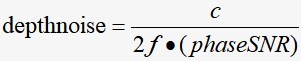 can be derived from the depth calculation formula of iToF,
 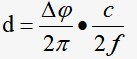 . Since the c corresponds to the speed of light and is a fixed value, the depth accuracy is related to the frequency of the modulated light and the phase signal-to-noise ratio (phase+SNR). When the phase signal-to-noise ratio is constant, the higher the frequency, the smaller the depth noise, which also means higher depth accuracy. The phase signal-to-noise ratio of iToF is related to the photocurrent received by the sensor,
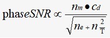 . Among the computational formula, nm represents the electrons generated by the modulated signal, ne represents the sum of the electrons generated by the modulated light and the ambient light, nT represents the inherent noise of the capacitor, and cd is the modulation contrast which describes the quality of the sensor to separate and collect photoelectrons. Therefore, the more electrons generated by the nm modulated light signal, the greater the phase signal-to-noise ratio, and thus the higher the depth accuracy. There are two ways to increase nm, one is to increase the illumination power, and the other is to extend the exposure time, that is, the integration time. In general, the current iToF depth accuracy is at the cm level.As the measurement distance increases, the intensity of the reflected light decreases, or the signal-to-noise ratio of the phase measurement decreases, the absolute error will increase accordingly.
2. Effective detection distance
The effective detection distance refers to the distance range in which the camera can output reliable depth. Reliable depth means that the error between the depth value and the true value is less than a certain threshold. For example, if the measurement error is within 2 cm, we consider the depth value to be reliable. If a ToF module measures an object at 5 meters, the measured value is 5.02 meters, and the error just reaches the pre-defined limit. When the object is at 5.01 meters, the measured value is 5.22 meters, and the error exceeds 2cm. We can say that the effective detection distance of the ToF module is 5 meters.
Of course, one of the main factors that limits the effective detection distance of ToF is the phase ambiguity phenomenon. For dToF, when the measurement distance is far, the time it takes for light to fly back and forth exceeds the interval between two consecutive pulse transmissions. The sensor receives the reflected wave of the first measurement signal only after transmitting the second measurement signal, and will mistake the reflected wave for the short-range reflected wave of the second measurement signal. At this time, phase ambiguity will occur. As shown in Figure 1. Case 1 in Figure 1 shows the ranging principle diagram of dToF in a close-range scenario, and case 2 shows the ranging principle diagram of a long-range scenario with phase ambiguity.
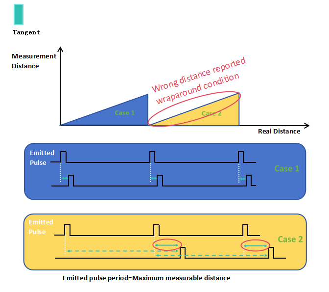
Figure 1. Schematic diagram of dToF pulse ranging principle
For iToF, the depth is calculated by phase offset,and the phase offset is obtained by an inverse tangent function  . The return value of the inverse tangent function will only fall on
  , so the return value of the measured depth will also fall on
 .In other words, even if the actual distance exceeds
 , the final output depth of iToF will fall on
  .This is due to the phase ambiguity caused by the periodicity of trigonometric functions.
dToF is limited by the measurement frequency (the interval between two adjacent measurements), and the effective detection distance of iToF is limited by the frequency of modulated light. When measuring distant objects, dToF can appropriately increase the interval between two measurements and reduce the number of measurements. However,reducing the number of measurements will also reduce the measurement accuracy, which is equivalent to exchanging accuracy for effective detection distance. iToF can also reduce the frequency of modulated light, thereby sacrificing a certain amount of measurement accuracy to obtain a longer effective detection distance.
For iToF, dual-frequency can be used to solve the phase ambiguity phenomenon. Use measurement data of two different frequencies to solve the phase ambiguity and restore the correct depth value. With the help of dual-frequency measurement, high-precision measurement and high effective detection distance can be achieved at the same time.
3. Image resolution
The image resolution of dToF is limited by SPAD, and the resolution is generally less than QVGA (320*240 pixels). The dToF resolution of the new iPad+Pro has been improved, but the specific size is still unknown. iToF technology is relatively mature, and the image resolution has mostly reached QVGA (320*240 pixels). The resolution of Shanghai data miracle intelligent's TC-S series cameras can reach VGA (640*480 pixels). Microsoft's latest Kinect has multiple image resolutions, up to 1024*1024 pixels.
4. Energy consumption
From the perspective of the transmission signal, dToF uses a +level pulse laser, and iToF currently mostly uses continuous wave modulation. In comparison, the pulse wave can achieve an ultra-low duty cycle, so the power consumption is also lower. From the perspective of the illumination mode, since the measurement accuracy of dToF will not decrease with the increase of the measurement distance, the power consumption will also be relatively low. On the contrary, iToF currently mostly uses surface light emission. Moreover, as the measuring distance increases, iToF needs to increase the light power or extend the exposure time to obtain higher accuracy, and the required power consumption will also increase significantly.
5. Cost
dToF uses a digital circuit architecture and does not require analog-to-digital conversion. iToF uses an analog circuit structure and requires an analog to digital conversion chip. As for the overall hardware architecture, the production process of dToF's core component SPAD is complicated and the existing resources are few. iToF has no such concerns. In terms of system integration, dToF also requires additional time to process circuits, and system integration of it is more difficult. iToF's system integration is easy and does not require additional measurement circuits.
6. Anti-environmental interference
Environmental interference includes ambient light interference in the scene, multi-path reflected light interference, and different surface grayscales.This type of environmental interference occurs in the outside world and has little to do with ToF itself.The difference in environmental interference is mainly caused by the ranging principles of different ToFs. When a single-frame depth map of dToF is acquired, it will undergo multiple repeated measurements, and the flight time is calculated by time histogram statistics, which makes it easier to distinguish the interference components in the signal. It has stronger anti-environmental interference ability. During the exposure stage of iToF, part of the ambient light is mixed in the modulated light and received by the sensor, and then the phase shift is calculated. It is impossible to distinguish the interference caused by ambient light from the results of a single measurement. The stronger the ambient light, the greater the depth error caused.
7. Application scenarios
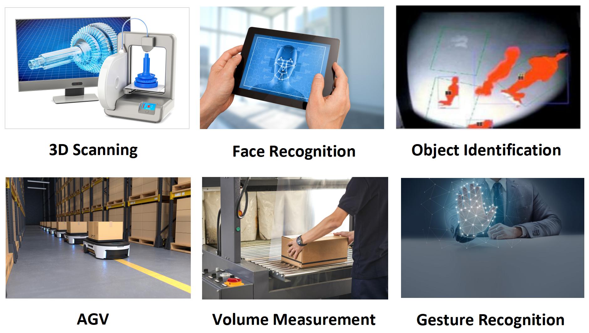
dToF has low power consumption and a small size, which is more suitable for applications such as industrial robots that require rapid ranging,obstacle avoidance detection,or some compact designs with limited space. dToF has a better performance in anti-environmental interference and higher ranging accuracy in outdoor scenes than that of iToF, thus dToF is more advantageous in outdoor application scenarios. dToF has high temporal resolution, as its accuracy and energy consumption will not significantly decrease when the measurement distance increases, its advantages in AR applications are also quite significant.
iToF has high image resolution reproducing more detailed information in application scenarios such as object recognition, 3D reconstruction and behavior analysis, alos has an advantage in robots and new retail fields.
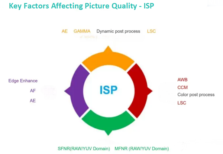
Since both dToF and iToF aim to output a high-quality depth image, both require filtering and noise correction at the depth data level, such as spatial filtering, noise filtering in the point cloud domain, and non-uniform pixel calibration. In addition, both have lens imaging systems, dToF and iToF require lens distortion compensation. The noise caused by the temperature change of the hardware also exists in both two ToFs, so temperature compensation is also necessary for both.The raw sensor depth data with noise can be optimized by ISP(Image Signal Processing)
as: ① Reliable and accurate depth data; ② Broadened application scenarios; ③ Higher cost performance of the system.
dToF transmits pulse waves, not modulated waves of a specific frequency, so dToF does not need to do frequency-related processing of modulated light, including frequency calibration, automatic frequency selection, and high dynamic range (HDR). However, the emission pulse of dToF also has a certain frequency, that is, the time interval between two adjacent emission pulses, and the frequency calibration of dToF is related to the frequency of the emission pulse. dToF only outputs a depth map, while iToF outputs both a depth map and an amplitude map, so dToF does not need amplitude calibration.
In addition, multi-path, phase blur, motion blur and internal reflection caused by scene interference are common problems for both iToF and dToF. Although dToF has better anti-environmental interference capabilities due to the characteristics of the imaging principle, it will still be affected by this kind of scene interference. However, because of the imaging principles difference, the depth correction methods required by the two will also be different.
In a summary, due to the differences in ranging principles and hardware architectures, dToF and iToF have their own advantages and disadvantages in various aspects. Their applicable scenarios are also different, both facing the adaptability of the scene. How to obtain reliable and accurate depth data in a certain scene is a very big technical challenge as well as the key to the popularization of ToF technology. The popularization of ToF application technology depends on the 3D+ISP enhancement engine to eliminate interference, reduce power consumption, and improve real-time performance; ISP+IP and middleware for the 3D industry are needed to strongly support upper-level applications. Therefore, 3D+ISP is a necessary condition for the outbreak of the 3D imaging market.
X-Dynamics
Tel: 86-027-65523090 86-13971451311
E-mail: Sales@x-dynamics.cn
Add:6F,Building C2,Wuhan Future Science
and Technology City,
No.999 Gaoxin Blvd, Wuhan
Hubei 430205, China
SAF Coolest v1.3.1.2 设置面板 HDISX-ABHT-YSZAE-DZF
无数据提示
Sorry, the current column is being updated, please look forward to it!
You can view other columns or returnHome Page